DFM for CNC Machining: 12 Rules That Cut Part Cost
Most of the cost of a machined part comes from machine time, setups and inspection rather than material. These 12 design rules target each of them without changing how the part works.
By the Axisform engineering teamPublished Updated 7 min read
The fastest way to cut CNC machining cost is to design parts that standard tools can make in few setups: add internal corner radii, keep pockets shallow, use standard hole and thread sizes, avoid thin walls, and tolerance only the features that function. Most cost on a machined part comes from machine time, setups and inspection, not raw material, so every rule below targets one of those three. Apply them during design, before the drawing is released, when changes cost nothing.
What is design for manufacturability (DFM) in CNC machining?
Design for manufacturability is the practice of shaping a part so that it can be produced reliably at the lowest cost without compromising function. For CNC machining, that means designing around the geometry of rotating cutting tools, the rigidity of the workpiece, the way parts are clamped, and the cost of measuring each feature.
DFM is not about making parts simpler at any price. It is about removing cost that does not add function.
The 12 DFM rules that cut CNC machining cost
1. Add a radius to every internal vertical corner
End mills are round, so they cannot cut a sharp internal vertical corner. A sharp corner requires EDM or a secondary process, which adds cost and time.
Make internal corner radii at least one-third of the cavity depth as a rule of thumb.
Make the radius slightly larger than the cutter radius (for example, a 3.2 mm radius instead of 3.0 mm for a 6 mm cutter). This lets the tool sweep the corner instead of plunging into it, reducing chatter and improving finish.
If a square part must fit into a pocket, use dog-bone or T-bone corner relief instead of a sharp corner.
2. Limit pocket and cavity depth
Long tools deflect and vibrate, so deep pockets need slow, light cuts.
Keep cavity depth to about 4 times the cavity width (or 4 times the tool diameter) for economical machining.
Deeper pockets are possible with long-reach tools but at much lower feed rates.
Use the largest internal radius you can accept, because that allows a larger, stiffer tool.
3. Keep walls thick enough
Thin walls vibrate, deflect under cutting forces and may warp.
Metals: aim for a minimum wall of about 0.8 mm, preferably 1.5 mm or more for tall walls.
Plastics: aim for about 1.5 mm minimum, more for tall walls, because plastics are less stiff and soften with heat.
Keep wall height-to-thickness ratios modest; tall, thin ribs are slow to machine.
4. Use reasonable hole depths
Standard drilling is economical up to about 4 times the diameter.
Up to about 10 times the diameter is common with peck drilling or longer drills.
Deeper holes need gun drilling or special tools.
Avoid flat-bottomed blind holes unless they are functional; a standard drill point (118° or 135°) is cheaper.
5. Use standard drill and reamer sizes
Standard metric (or fractional inch) drill sizes are always in stock. An odd size, such as 5.37 mm, must be interpolated with an end mill, which is slower and less accurate for small holes. For precision holes, use standard reamer sizes and fit codes such as H7.
6. Limit thread depth and use standard threads
Thread strength comes mostly from the first few engaged turns.
Thread engagement of 1.5 times the nominal diameter is usually sufficient for steel; around 2 times in aluminum and other softer materials.
Engagement beyond about 3 times the diameter adds little strength but increases tapping time and tap breakage risk.
For blind holes, leave unthreaded length at the bottom (roughly a few thread pitches) so the tap does not bottom out.
Use standard metric coarse or UNC/UNF sizes. Small taps (M2 and below) break easily and are slower.
7. Tolerance only what matters
Tight tolerances require slower cuts, extra inspection and more scrap risk. Use a general tolerance standard such as ISO 2768-m in the title block and individual tolerances only on fits, sealing faces and locating features. Our CNC tolerance guide explains the cost steps between ±0.05, ±0.01 and ±0.005 mm.
8. Minimize the number of setups
Each time a part is re-clamped, the operator spends time on fixturing and the machine sits idle. Re-clamping also introduces small location errors between features.
Place features on as few faces as practical.
Align holes and pockets with the main axes.
Consider whether a feature on the side could be moved to the top.
Undercuts need special cutters (T-slot, dovetail or lollipop tools). If an undercut is necessary:
Use standard cutter widths and depths.
Leave clearance around the undercut so the tool can enter.
Consider whether the part could be split into two simpler parts.
10. Keep text and engraving simple
Use bold, sans-serif fonts, and avoid small characters (under about 2–3 mm high) where possible.
Engraved (recessed) text is cheaper than embossed (raised) text, which requires machining all surrounding material.
For markings on anodized or coated parts, laser marking is often cheaper and sharper than machined engraving.
11. Choose materials and stock sizes deliberately
Use common alloys (6061-T6, 304 stainless, 1045 steel, POM) unless the application needs something else. Read 6061 vs 7075 aluminum for a typical trade-off.
Size parts so they fit standard bar or plate dimensions with a small machining allowance; a part that is 0.5 mm larger than a standard plate thickness forces the next stock size up.
Free-machining grades such as 303 stainless and C36000 brass machine faster than their general-purpose counterparts when their properties are acceptable.
12. Specify surface finish and cosmetic requirements only where needed
As-machined finish (about Ra 3.2 µm) is standard and adds nothing.
Ra 1.6 µm needs finishing passes; Ra 0.8 µm or better may need special tooling, grinding or polishing.
Mark cosmetic faces (A-surfaces) on the drawing so tool marks and handling are controlled only where they are visible.
Specify edge treatment ("break all sharp edges 0.2–0.5 mm") instead of individual chamfers everywhere.
DFM rules summary table
Feature
Recommended guideline
Why it saves cost
Internal vertical corners
Radius ≥ 1/3 of depth, slightly larger than tool radius
Allows standard end mills, no EDM
Pocket depth
≤ about 4× width
Rigid tools, faster feeds
Wall thickness
≥ 0.8 mm metal, ≥ 1.5 mm plastic
Less chatter and distortion
Hole depth
≤ 4× diameter standard, ≤ 10× possible
Standard drills, no gun drilling
Hole sizes
Standard drill and reamer sizes
Off-the-shelf tools
Thread engagement
1.5–2× diameter, max ~3×
Less tapping time, fewer broken taps
Tolerances
ISO 2768-m general, tight only on functional features
Less inspection, less scrap
Setups
Features on fewest faces
Less handling and fixturing
Undercuts
Avoid or use standard cutter sizes
No custom tools
Text
Engraved, bold, ≥ 2–3 mm
Faster, more legible
Material
Common alloys, standard stock sizes
Lower material cost, faster availability
Surface finish
Ra 3.2 µm default, finer only where needed
Fewer finishing passes
What other design details affect cost?
Fillets on external edges often cost more than chamfers, because a chamfer can be cut with one tool along the edge while a 3D fillet may need a ball-end tool or a special corner-rounding tool.
Finishing allowances. Anodizing, plating and powder coating add thickness. Account for it on fits and threads — see our anodizing guide.
Part splitting. A complex monolithic part can sometimes be cheaper as two simple parts bolted or pressed together.
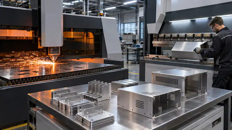
Process alternatives. For enclosures and brackets with uniform wall thickness, sheet metal may be cheaper than machining from solid. See sheet metal fabrication vs CNC machining.
How should you check a design for manufacturability?
Review each feature against the rules above before releasing the drawing.
Mark critical-to-function features so the supplier understands which tolerances are non-negotiable.
Ask the supplier for a DFM review with the quote. A good supplier will flag features that drive cost and suggest alternatives without changing function.
For new designs, make one or a few prototypes before ordering production quantities.
Axisform reviews drawings for manufacturability as part of the quoting process and points out features that drive cost. Prototypes start at one piece. Send your STEP file and drawing through our contact page.
Frequently asked questions
What is the minimum internal corner radius for CNC machining?
It depends on the tool and depth, but a common guideline is a radius of at least one-third of the cavity depth and slightly larger than the cutter radius. Very small radii are possible with small tools, but they increase machining time significantly.
How deep can a CNC machined hole be?
Standard drilling is economical up to about four times the diameter, and up to about ten times is common with peck drilling. Deeper holes require gun drilling or special tooling, which adds cost.
What is the minimum wall thickness for CNC machined parts?
A practical minimum is about 0.8 mm for metals and 1.5 mm for plastics. Thinner walls are possible on small, short features, but they tend to vibrate, deflect and distort during machining.
How deep should a tapped thread be?
For most applications, thread engagement of 1.5 times the diameter in steel and about 2 times in aluminum is sufficient. Threads deeper than about 3 times the diameter add little strength but increase machining time and risk.
Written by the Axisform engineering team
Manufacturing and quality engineers at our Dongguan machining factory. Questions about this guide? Email us.
Need parts made to these principles?
Send your drawing and an engineer will reply with DFM notes and a quote within 24 hours.
A good metal knob depends as much on its bore fit and runout as on its finish. This guide covers knurling patterns, materials, finishes and the main ways knobs attach to shafts in audio, appliance and automotive controls.
Sheet metal is usually cheaper for uniform-wall enclosures and brackets, while CNC machining wins on varying thickness and tight tolerances. This guide compares both and explains bend radius and K-factor basics.
Most quality problems with imported machined parts come from requirements that were never written down. This guide walks through the RFQ package, first article approval, inspection documents, Incoterms and shipping.