New Energy
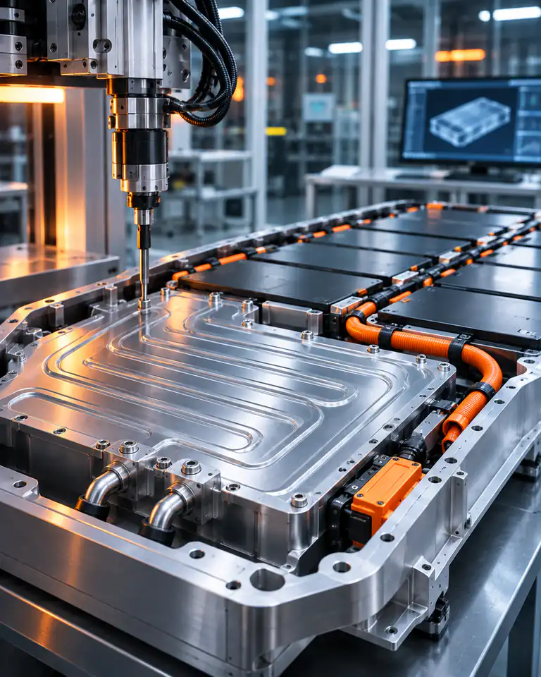
CNC Machined Battery Cooling Plates and Housings in 6061-T6
An energy-storage customer needed a liquid-cooled battery plate and its matching housing machined from solid 6061-T6 for a prototype pack.
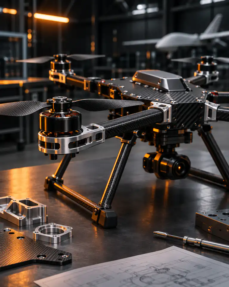
A UAV developer needed motor mounts and arm-to-frame brackets for a multirotor airframe, machined from 7075-T6. The parts had to be as light as possible while keeping the motor face flat, the bolt pattern accurate and the carbon tube clamp sized to grip without crushing the tube.
On a multirotor, every gram on the arm tip counts, and the motor mount sits at the end of the arm. The customer's design used deep pockets and ribs down to 1.2 mm thick to remove weight, which brings the usual thin-wall problems: chatter, deflection under the cutter and distortion after unclamping.
At the same time, the mount has functional features that cannot move:
The bracket at the frame end had similar clamp bore requirements plus a mounting pattern that had to match the frame plates. Each part also had a target mass on the drawing, so extra material left for safety was not an option.
We sequenced operations so the thin ribs were cut last, when the stiff features were already finished.
The bracket used the same sequence, with the frame mounting pattern and clamp bore finished together.
Inspection covered fit, flatness and mass.
Clamp bore, motor face flatness and mass were 100% inspected on the pilot run. Material certificates for the 7075-T6 stock were included.
We delivered prototype motor mounts and brackets for the first airframe build, followed by a pilot run on the same fixtures and programs. The delivery included:
Each part was serial marked so its mass and dimensional record could be traced during the build. Flight testing and vibration evaluation were carried out by the customer on their airframe.
Ribs around 1.0–1.5 mm are practical in 7075-T6 when the rib height is moderate and the pocket corner radii allow a short, stiff cutter. Very tall, thin ribs vibrate under the tool, so rib height-to-thickness ratio is reviewed during DFM.
7075-T6 has a high strength-to-weight ratio and machines cleanly, which allows thin sections without losing stiffness. It is less corrosion resistant than 6061, so it is normally anodized.
An energy-storage customer needed a liquid-cooled battery plate and its matching housing machined from solid 6061-T6 for a prototype pack.
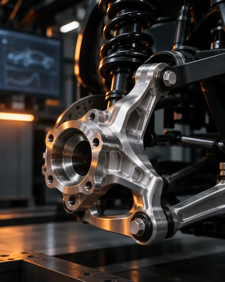
A chassis development team needed suspension knuckles machined from billet so they could test a new geometry before committing to forging tools.
Similar part?
Send your drawing and we’ll reply with a process plan and quote.