New Energy
CNC Machined Battery Cooling Plates and Housings in 6061-T6
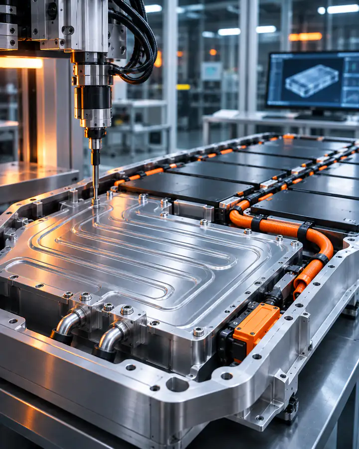
An energy-storage customer needed a liquid-cooled battery plate and its matching housing machined from solid 6061-T6 for a prototype pack.
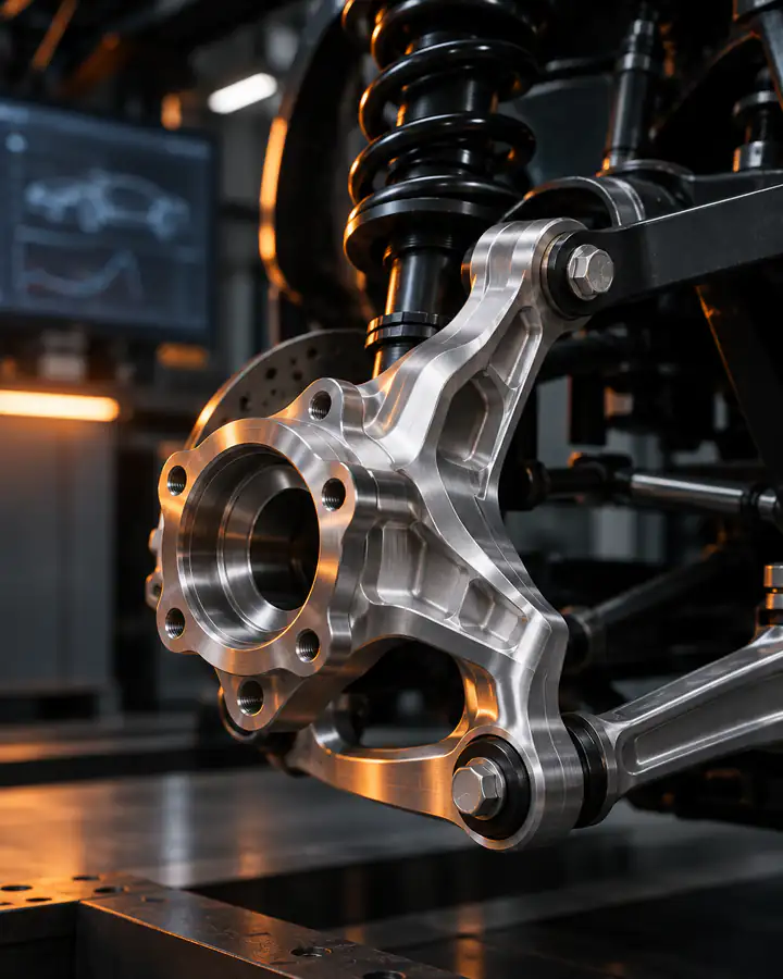
A chassis development team needed suspension knuckles machined from billet so they could test a new geometry before committing to forging tools. The job was to hold the hub bearing bore, ball-joint taper and strut mounting points in correct relation to each other on a part with few flat surfaces to clamp.
A suspension knuckle connects the wheel bearing, brake caliper, steering arm, lower ball joint and strut. Each of those interfaces has its own feature, and they all have to sit in the right place relative to one another, because the knuckle defines camber, caster and steering geometry.
Key requirements on the drawing:
Production knuckles are usually forged or cast and then machined. For a prototype, the customer wanted billet parts in 7075-T6 so that they could change the design between iterations without tooling cost. That means a large block is reduced to an organic, ribbed shape, and the part must be held securely through operations without distorting thin webs.
We planned the job so that every critical feature was machined from as few datums as possible.
Toolpaths for the organic surfaces used constant-scallop finishing so the blend radii carried no step marks that could become stress risers.
Because the knuckle sets wheel geometry, inspection focused on relationships between features, not only individual sizes.
Every pilot-run knuckle received 100% inspection of the bore, taper and hole positions, with a serial number laser marked on a non-functional face.
We delivered the prototype knuckles and a follow-up pilot run made on the same fixture and program. The delivery package included:
The customer used the parts for fit and vehicle testing. Design changes between iterations were handled by updating the model and toolpaths, with the same datum scheme kept so reports remained comparable from one revision to the next.
Billet machining needs no forging die, so the design can change between test iterations at the cost of programming time only. Once the geometry is frozen, the same datum scheme can be used to machine forged or cast blanks.
H7 is an ISO 286 hole tolerance class. The bore can be at nominal size or slightly larger, never smaller. For a bore in the 50–80 mm range, H7 allows 0 to +0.030 mm, which gives a controlled press fit with a standard bearing.
An energy-storage customer needed a liquid-cooled battery plate and its matching housing machined from solid 6061-T6 for a prototype pack.
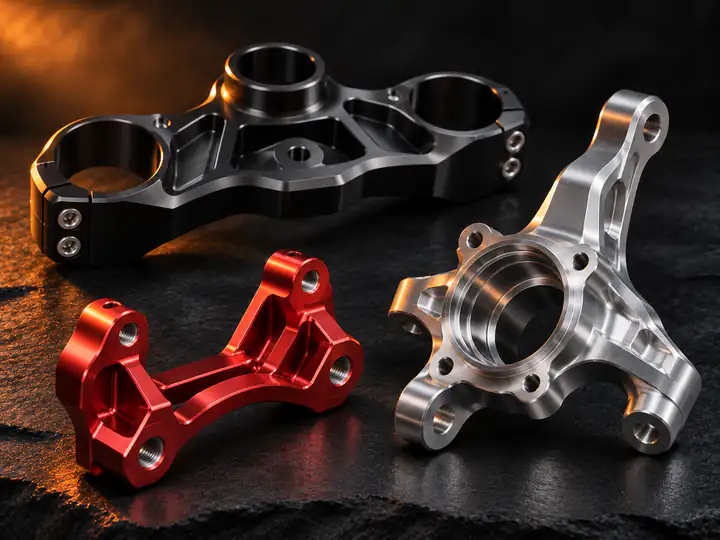
A cycling and powersports components customer needed a handlebar stem and a rear-suspension linkage machined from 7075-T6 for a new product line.
Similar part?
Send your drawing and we’ll reply with a process plan and quote.