New Energy
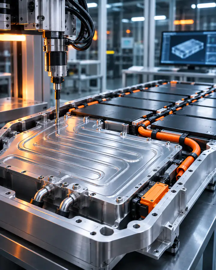
CNC Machined Battery Cooling Plates and Housings in 6061-T6
An energy-storage customer needed a liquid-cooled battery plate and its matching housing machined from solid 6061-T6 for a prototype pack.
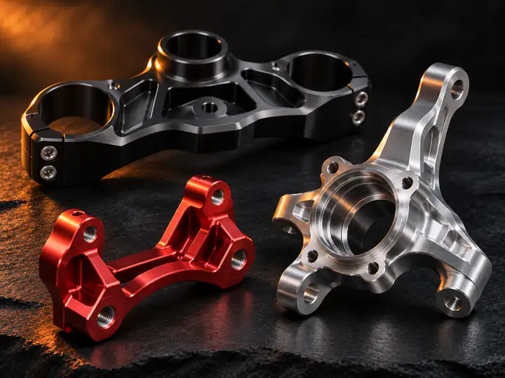
A cycling and powersports components customer needed a handlebar stem and a rear-suspension linkage machined from 7075-T6 for a new product line. Both parts are lightweight structural pieces where clamp bore sizes, pivot alignment and edge quality matter as much as appearance.
Stems and suspension linkages look simple, but they are highly loaded parts that the rider sees up close.
For the stem, the steerer clamp (Ø28.6 mm, the 1-1/8 in standard) and the handlebar clamp (Ø31.8 mm or 35 mm, depending on the bar) must be sized so the clamp closes evenly around the tube. A bore that is too tight can crush a carbon steerer; one that is too loose concentrates load at the bolt side. The slot edges and the inner bore edges must be smooth, with no sharp corners that start cracks.
For the linkage, two or three pivot bearing seats must be parallel and at the correct center distance, because the linkage defines the suspension leverage curve. Bearing seats for press-fit cartridge bearings need a fit that holds the bearing without distorting it.
Both parts also carry a cosmetic requirement: uniform bead-blasted texture and an even black anodize, with no visible tool steps on the curved surfaces.
We split the work by part type but used the same principle for both: finish all related features in one setup.
Stem process route
Linkage process route
Finishing for both
Parts were bead blasted for an even matte texture, then Type II black anodized. Bearing seats were sized with the anodize growth in mind and the bores were plugged during coating so their size stayed as machined. Logos and part numbers were laser marked after anodizing.
Inspection focused on the features that affect safety and fit.
All critical dimensions were 100% inspected before shipment, and material certificates for the 7075-T6 stock were included in each delivery.
We delivered prototype stems in several lengths and a set of prototype linkages, followed by a low-volume production order made on the same fixtures and programs. Each delivery included:
Strength and fatigue testing of the stems and linkages was carried out by the customer according to their own test standards.
7075-T6 has a typical yield strength around 500 MPa, compared with about 275 MPa for 6061-T6. That allows thinner sections at the same strength, which is why it is common for stems and linkages where weight matters. 6061-T6 is easier to anodize evenly and costs less.
All pivot bores are bored in a single clamping on the 5-axis machine. Because the part is not moved between bores, parallelism and center distance depend only on machine accuracy, and are then verified on CMM.
An energy-storage customer needed a liquid-cooled battery plate and its matching housing machined from solid 6061-T6 for a prototype pack.
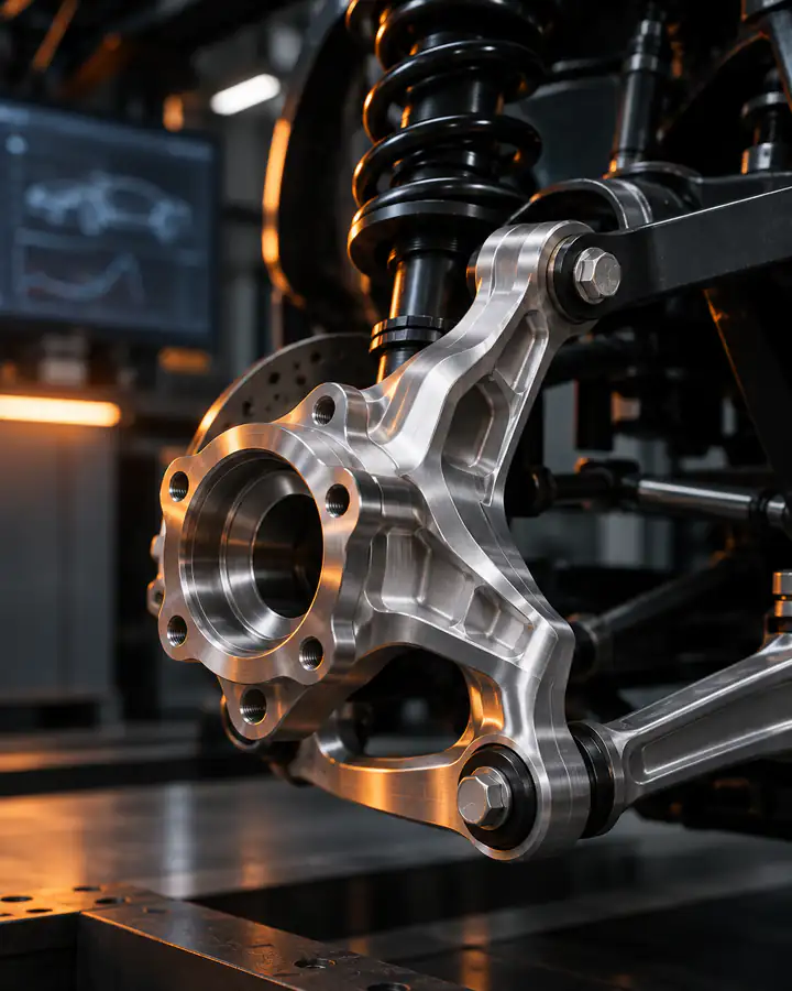
A chassis development team needed suspension knuckles machined from billet so they could test a new geometry before committing to forging tools.
Similar part?
Send your drawing and we’ll reply with a process plan and quote.